Application of ANAPF Active Filter Device in 0.4KV Distribution System of Small and Medium-sized Enterprises
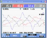
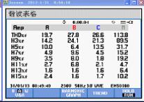
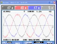
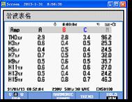
1 Introduction As the power electronics technology continues to mature, non-linear devices such as energy-saving lamps, computers, and copiers are increasingly used in residential and office buildings. Harmonic pollution in low-voltage power distribution systems is increasingly serious, and power companies and users The demand for power quality is getting higher and higher, and the harmonic problem has attracted more and more people's attention. Effectively controlling harmonics and controlling them within permissible limits has become an issue that power workers must consider. 2 Main Harmonic Pollution Sources in Low Voltage Distribution Systems When a sine wave voltage is applied to a non-linear load, the current becomes a non-sinusoidal wave, and the non-sinusoidal current produces a voltage drop across the grid impedance, which causes the voltage waveform to also become a non-sinusoidal wave. Fourier series decomposition of non-sinusoidal wave, in which the frequency and the same frequency component is called the fundamental wave, the frequency is greater than the frequency component is called harmonics. Most of the widely used loads today are nonlinear, such as rectifiers, inverters, electric arc furnaces, welding equipment, UPS, elevators, air conditioners, energy-saving lamps (fluorescent lamps), copiers, etc. These nonlinear loads generate a large amount of harmonic currents. It is injected into the power grid and causes distortion of the grid voltage. This harmonic pollution will cause serious damage to the power grid and users. 3 Harmonic Harm to Low Voltage Distribution System Increase the loss of transmission lines and shorten the life of transmission lines; increase the copper and iron consumption of transformers and reduce the output of transformers; cause malfunction or refusal to operate power distribution devices, resulting in blackouts; affecting motor efficiency and normal operation, resulting in vibration and noise, Reduce motor life; cause harmonic amplification or resonance problems; cause errors in various measurement instruments in the power system; interfere with communication systems and damage sensitive equipment; cause large currents on neutral lines and cause system failures. 4 Harmonic control measures for low voltage distribution network There are two major harmonic control measures for low-voltage power distribution networks. One is active measures, starting from the harmonic source itself, so that it does not produce harmonics or reduce the harmonic content of its output; the second is passive measures, ie Install power filters to filter out harmonics generated by harmonic sources, or to prevent harmonics of the power system from flowing into the user's power grid. Active measures include multi-pulse rectification, pulse width modulation (PWM), matrix converters, four-quadrant converters, and more. The use of active measures can effectively limit the generation of harmonics, but due to the diversity of non-linear loads, it is impossible to completely eliminate harmonic currents through active measures. Passive measures mainly include PPF and the APF that has emerged in recent years. PPF has been widely used because of its low cost, simple structure, and easy maintenance. However, it has some disadvantages that are difficult to overcome, such as filtering only harmonics of specific frequencies, easy parallel resonance with the system, and filtering for fluctuating loads. The effect is not ideal. APF has the characteristics of fast response, strong filtering ability, flexible installation, and easy expansion. It has been more and more widely used in recent years. 5 APF (active power filter) principle introduction and features ANAPF series active power filter devices are connected to the power grid in parallel and detect harmonics and reactive components of the load in real time. PWM inverter technology is used to generate one current harmonic component and reactive component from the converter. The reverse component is injected into the power system in real time, so that harmonic control and reactive power compensation are achieved. The principle is as follows: ANAPF not only has the function of filtering harmonics, but also can provide advanced or delayed reactive current for improving the power factor of the power grid and realizing dynamic reactive power compensation. At the same time, it also has the function of compensating three-phase unbalance to reduce the current flowing through the neutral line. ANAPF uses the instantaneous reactive power theory to extract harmonic components within 20 μs in response to changes in load. The full response time is 20 ms and can be used in applications where the load fluctuates rapidly. ANAPF can compensate 2nd to 50th harmonics. ANAPF has an automatic current limiting function that does not overload. ANAPF has complete protection measures to ensure safe operation of equipment. ANAPF has powerful customization capabilities. It can be set to only compensate for harmonics, only compensate for reactive power, or both. ANAPF adopts large-capacity, high-definition human-machine interface color touch screen, which can display various electrical parameters such as voltage, current, harmonics, power factor, etc. of the system in real time. The menu is displayed in Chinese, with illustrations, real-time display of device operating parameters and historical event records. The display interface can be set by touch, and the operation is simple and quick. ANAPF is simple in design selection and does not require detailed grid analysis. It only needs to measure harmonic currents. ANAPF is simple and easy to install, easy to expand, and can be flexibly selected according to the actual conditions of the load and distribution system, as well as the expected compensation effect, and different forms of installation compensation can be used, making the investment less effective. According to the different installation locations of ANAPF, it can be divided into two forms: comprehensive compensation and local compensation. ANAPF has two series of three-phase three-wire and three-phase four-wire. Its capacity is 50A, 100A, and 150A, which can meet the needs of different users. 6 Main Technical Specifications of APF (Active Power Filter) Wiring Three-phase three-wire or three-phase four-wire Access voltage 3×380V ±10% Access frequency 50Hz ±2% Dynamic compensation response time Dynamic response <4ms, full response time <20ms; On-off level 10kHz Function settings Only harmonics are compensated, only reactive power is compensated, both harmonics are compensated and reactive power is compensated; manual and automatic switching are performed. Harmonic compensation times 2-21 times Type of protection DC over-voltage IGBT over-current device temperature protection Overload protection Automatic current limit in the set value, no overload occurs cooling method Smart air cooling noise < 65db (in the cabinet and operating in the rated state) Working temperature -10°C to +45°C Working environment humidity <85%RH non-condensing Installation occasion Indoor installation Altitude ≤1000m (for use at higher altitudes) Incoming and outgoing ways Down in and out Protection level IP21 Intelligent communication interface RS485/MODBUS-RTU Remote monitoring Optional Overall size (mm) (W×D×H) 30A 50A 75A 100A 600×500×1500 600×500×1500 600×500×1800 800×600×2200 Weight (kg) Three-phase four-wire Three-phase three-wire 30A, 50A 75A, 100A 30A, 50A 75A, 100A 280 360 240 290 7 ANAPF Active Filter Quotes and List of Major Components Model Number: ANAPF50-400/B Reference price: 75,000 yuan/set The main product details: No. Name Model number Quantity 1 APF electrical cabinet 600X500X1800 1 2 Converter APFCOV-CVT50 1 3 Controller APFMC-C50 1 4 Reactor APF-RE.(S)DG-50 1 5 Active current transformer LT 1 08-S7 3 6 filter DL-1TH1 2 7 breaker NSE100N4063 1 8 Contactor LC1D65 M7C 1 9 MCB NDM1-63C32 1 10 Intermediate relay MY4NAC 2 11 R type transformer R320-0.38/0.22 1 12 Harmonic Detector ACR350EGH 1 13 wire 16mm 2 Some 14 wire 4mm 2 Some 8 Application of ANAPF in Low Voltage Distribution System A small and medium-sized enterprise in Shanghai has a transformer capacity of 150 kVA. When a large number of air conditioners are turned on at the same time during the winter, the circuit breaker will trip, seriously affecting the company's daily operations. After investigation, the company has a large number of non-linear loads such as energy-saving lamps, inverter air conditioners, computers, printers, and elevators. It is these nonlinear loads that reduce the output of the transformer. Studies have shown that harmonic currents can cause the outer shell of the transformer shell or some of the fasteners to heat, which may cause local overheating, accelerate the aging of the dielectric, cause damage to the insulation, and reduce transformer life. The presence of harmonics will increase the apparent power. Regardless of harmonics, the relationship between apparent power S and active power P and reactive power Q is Using FLUKE 434 to measure the lighting loop to get the current waveform shown in Figure 1. As can be seen from the figure, the current waveform is far from the ideal sine wave, and distortion is more serious. Distortion of the current waveform can cause distortion of the voltage waveform and affect the normal operation of other devices such as computers. At the same time, the N-phase current reached 37A, the current imbalance problem is also more prominent, and there is a greater potential for electricity hazards. The harmonic content data is shown in Figure 2. As can be seen from the figure, THD i of phase A, phase B, and phase C is 19.7%, 27.8%, and 26.6%, respectively. Harmonic pollution is very serious and there are potential safety hazards. Figure 1: Lighting loop current waveform Figure 2: Lighting loop subharmonic content data According to the harmonic content, select the ANAPF with a rated capacity of 50A to compensate the lighting circuit separately. The current waveform and the fractional harmonic content data obtained after the control are shown in Figure 3 and Figure 4, respectively. Fig. 3: Current waveforms of the lighting circuit after treatment. Fig. 4: Harmonic content data of the lighting circuit after the treatment. From Fig. 3 and Fig. 4, it can be seen that after the control, the current waveform is close to the perfect sine wave, the distortion of the current becomes effective control, and the neutral current is also reduced from 37 A to 5 A, eliminating the excessive current due to the neutral current. As a result of the fire hazards, the harmonic content of the current is reduced from about 20% to about 3%, and the harmonic content is greatly reduced. It has met the requirements of the GB T14549-1993 “Power Quality Harmonics in Public Power Gridsâ€. ANAPF effectively reduces THD i while suppressing three-phase imbalance, reducing the current flowing through the neutral wire, effectively increasing various energy indexes, enabling normal operation of various electrical equipment, and extending the equipment The service life reduces the losses due to circuit failures. Through this data collection and analysis, a large amount of reference data has been accumulated, laying a solid foundation for future harmonic management. [references] [1] Wang Zhaoan, Yang Jun, Liu Jinjun. Harmonic Suppression and Reactive Power Compensation [M]. Beijing: Mechanical Industry Press, 1998 [2] China National Standard of the People's Republic of China GB/T14549- 1993. Power Quality Harmonics in the Public Power Grid [S]. Beijing: China Standard Press, 1994. [3] Luo An. Harmonic Harmonic Control and Reactive Power Compensation Technology and Equipment [M]. Beijing: China Electric Power Press, 2006 Aerogel Insulating Solutions,Silica Aerogel For Buildings,Aerogel Insulating Plaster,Silica Aerogel Insulation Henan Minmetals East New Materials CO. LTD. , https://www.materials-silicon.com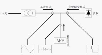
 In the presence of harmonics, the harmonic power D must be taken into account.
  ; And D and Q, can not be converted into useful power. It can be seen that harmonics have a significant negative impact on the efficiency of transformer use. The actual survey and analysis found that the company's transformer margin is not large, but if the harmonics are reduced to meet the scope of national standards, it can meet the daily power supply needs, there is no need to expand capacity. The investigation and analysis of the company's electricity load revealed that the lighting circuit has a large load, and because the lighting circuit uses a large number of energy-saving lamps, the loop harmonic content is relatively high, which is the main reason for reducing the transformer output.