The lightning protection grounding device is a concealed project. It is divided into the following stages: detection at the construction stage and periodic inspection at the use stage. The detection at the construction stage mainly tests the grounding material specification, layout, depth, welding quality, and anti-corrosion measures. Grounding resistance and so on.
Because the grounding body is buried in the ground and needs to work stably for decades, it is not easy to maintain the construction, so the material specification is particularly important. Must use good quality galvanized (hot dip galvanizing process) steel, galvanized angle iron, galvanized steel needle, galvanized flat steel, etc. to ensure thick and thick. The arrangement of the artificial grounding body must take into account the collective effect of the parallel grounding poles whose lightning current amplitude is large and exceeds the power frequency current, that is, the distances of the vertical grounding bodies should not be too close, otherwise the grounding resistance obtained by the test meets the requirements, The effect of diffusing in the ground is not always good. The distance between the vertical grounding body is generally 2 times the length of the vertical grounding body. The minimum is 1.5 times.
The general standard or specification stipulates the allowable value of the impulse grounding resistance of the lightning protection device, and usually the test meter tests the frequency-frequency grounding resistance (because the portable grounding resistance tester is not easy to generate large simulated lightning current test waveforms, thus it is not easy to generate lightning. The impact of the current in the ground is grounded to the physical process, so currently there is no truly impregnable grounding resistance tester on the market). Since lightning currents are very powerful inrush currents, their amplitudes are often as large as tens of thousands or even hundreds of amps. In this way, the current density flowing through the grounding device is increased, and is affected by the inductance due to the current impact characteristics. At this time, the grounding resistance is called an impact grounding resistance.
Due to the increase of the current density flowing through the grounding device, spark discharge occurs in the air gap in the soil and the gas layer between the ground electrode and the soil. This results in a decrease in the resistivity of the soil and a decrease in the soil and grounding electrodes. The contact area increases. As a result, it is equivalent to increasing the size of the ground electrode and reducing the impact resistance value. That is to say, due to the spark effect of the lightning current (if the spark effect is greater than the inductive effect), the ground frequency resistance of the same grounding body is generally greater than the impact ground resistance: R,,, =AR; (A) 1), so Under the circumstances, if the test result shows that the frequency-to-ground resistance value meets the requirements of the grounding resistance value in the lightning protection standard, it is not necessary to perform the conversion to directly determine that it is qualified. otherwise. The frequency limit grounding power limit should be converted into the impact grounding resistance value, even considering the seasonal factor, etc., and then compared with the specification requirements, so as to determine whether it is qualified. In this case, especially in the test result, the power frequency grounding resistance value exceeds the allowable value of the grounding resistance. More situations are useful and necessary.
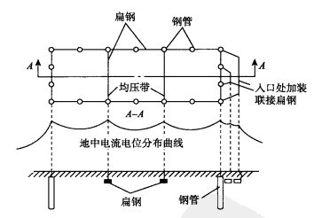
In the range of 3m away from the grounding body, due to the large gradient, the human body is in danger of electric shock caused by the step voltage. Therefore, the outer edge of the artificial grounding net should be closed, and the outer edges should be rounded to form a circle. The radius of the arc should not be less than half the spacing of the horizontal grounding band (which can act as a pressure equalizer). At the edge of the grounding grid, people are often at the person's aisle. Gravels, asphalt pavement, or "cap gun type" equalizing belts (see Figure 3.1) should be used to improve the distribution of ground potential.
Figure 3.1 Add Equalizing Bands to Evenly Distribute Potential
In corrosive soils, anti-corrosion measures such as hot-dip galvanizing or cross-sections should be adopted. Cathodic protection measures can also be used. The theory of cathodic protection technology is that the corrosion occurred in the grounding device is basically electrochemical corrosion, so electrochemical protection can be used in the anti-corrosion protection measures. Electrochemical protection is the protection of metal components by polarization to an erosion or passivation zone. Electrochemical protection is divided into cathodic protection and anodic protection. The cathodic protection is to make the metal member act as a cathode and eliminate the electrochemical non-uniformity of the metal surface by cathodic polarization to achieve the purpose of protection. Cathodic protection is an economic and effective protective measure. Some grounding bodies that are required to be used in seawater and soil use cathodic protection, which can effectively increase their corrosion resistance.
Cathodic protection can be achieved by two methods: one is the sacrificial anode method and the other is the impressed current method. The sacrificial anode method is to attach a more negative metal or alloy to the protected metal. As a sacrificial anode, the current produced by its continuous dissolution is cathodically polarized by the protected metal, reaching the month of protection.
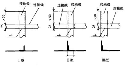
The inspection of the welding process and the welding quality during the construction of the grounding body is now taken as an example of the connection of the angle steel grounding electrode and the flat steel grounding wire. As shown in Fig. 3.2, there are three ways to use welding between the grounding electrode and the grounding wire. In order to ensure the connection strength, continuous welding should be performed around the wire. After welding, the welding slag should be removed and an asphalt paint should be applied on the welding site. (In the actual grounding project, after the welding value is used, only the welding point is removed, and the entire welding point is coated with the asphalt block while hot.) The welding of round steel, flat steel, and steel pipe grounding poles is similar to that of flat steel. When the grounding electrode is buried in a soil slope that may be chemically corrosive, the connection between the grounding electrode and the connection to the flat steel should be increased. Each welding head must be coated with glass cloth and coated with bituminous oil in order to enhance corrosion resistance. When the steel and round steel are overlapped, the overlapping length of the double-sided welding should not be less than 6 times the diameter of the round steel, and the length of the overlapping of the single-sided welding should be not less than 12 times the diameter of the round steel. When the round steel is connected with the flat steel The lap length is also 6 times the diameter of the round bar. The connection between flat steel and flat steel is not allowed to use butt welding and lap welding should be adopted. The lap length is 2 times the width of flat steel.

Figure 3.2 Connection method of grounding electrode and connecting wire (mm)
The grounding pole is L50x5, L=2500. The connecting line is flat steel 25x4. The wet area is 40x4.
Cold drawn, Peeled or Turned Ground and Polished Steel Bar
Peeled or turned steel bar is produced by peeling or turning from Hot Rolled Steel Bar. Our advantages and more services of Cold Drawn Steel Round Bar includes:
1) Wide range of diameters from 20mm to 150mm
2) Customized Length from 100mm to 12000mm
3) Good surface roughness: 0.4um to 1.6um
4) Good straightness: 0.5mm/m to 2mm/m
5) Good roundness: 80% of diameter tolerance
6) Diameter tolerance: -0.02mm to -0.1mm / h9, h10, h11
7) Matched further processing: Grinding, polishing, straightening
8) Anti-rusty package
9) Full sets of testing equipment: Surface, Dimenstion. Mechanical properties testing
10) Fast delivery time

