Grab Ship Unloader Drive System Design Based on ABB Inverter
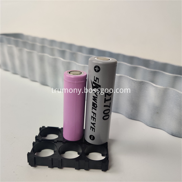
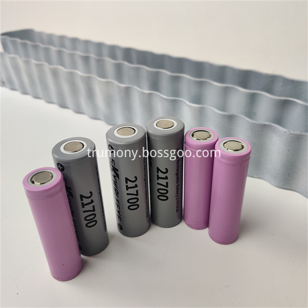
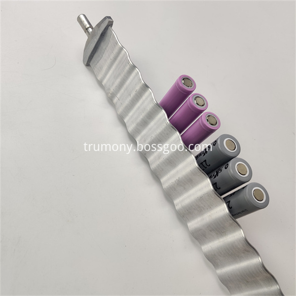
Snake tube, also named serpentine tube, one of Cooling Pipe which is using to exchange heat from battery to coolant to cool battery in EV industries.
It`s suitable for cylindrical battery thermal management, such as 18650, 2170,4680,46950... If for 32700 cell cooling, cooling pipe size can be 50~55mm, thickness can be 2~3mm, so all products are all customized, according to customers' battery pack, drawing and thermal data. And we have our R&D team, can provide design service.
water cooling tube,cooling plate for ev battery,cooling plate for prismatic cells Trumony Aluminum Limited , https://www.szaluminumplate.com
1 Introduction With the continuous improvement of the crane speed control performance of industrial production, the traditional crane speed control methods such as: wound rotor asynchronous motor series resistor speed control, thyristor stator voltage regulator and cascade speed, they are common The disadvantage is that the wound rotor asynchronous motor has collector rings and brushes, which require regular maintenance, coupled with the use of a large number of relays, contactors, resulting in a large amount of on-site maintenance, a higher failure rate of the speed control system, and speed The system's comprehensive technical indicators are poor.
The wide application of AC variable frequency speed regulation technology in the industry has provided a brand-new solution for large-scale, high-quality speed control of AC asynchronous motor-driven cranes.
ABB's new concept product, ACS800 series inverter, is used to control AC motors from 1.1 to 2800 kW. It has high-performance speed regulation indicators and can use a squirrel-cage induction motor with a simple structure, reliable operation, and easy maintenance. It is highly efficient, energy-efficient, and maintenance work. Small amount, perfect protection and monitoring functions, and greater reliability in operation than traditional AC speed control systems. Another big advantage is the uniform use of the same control technology in the full power range, such as start-up wizard, custom programming, DTC control, universal spare parts, universal interface technology, and general-purpose software tools for selection, commissioning and maintenance. . This improvement made the full series of accessories reach the maximum unity and brought huge economic benefits to the user.
2 Grab Bucket Unloader Schematics, Working Process and Requirements for Rotary System Grab Bucket Unloader is one of the important equipments for loading and unloading bulk cargoes in terminals of large ports, power plants, metallurgy and chemical industries. Loading and unloading of bulk cargoes such as coal, ore, cement, chemical raw materials, and grain.
Its main working process is to pick up bulk cargo from the ship and transport it to the conveyor belt on the shore. In the course of its movement, it mainly includes transmission points such as lifting, opening and closing, pitching, carts, and trolleys, which are respectively driven by separate control units and inverter units, and have high requirements for the control accuracy of the inverter.
The core technology of ACS800 frequency converter is direct torque control (DTC), which is the advanced AC asynchronous motor control method in industrial applications. DTC's outstanding performance and ABB's dedicated control macros for various industrial applications make ACS800 inverters suitable for various fields and have outstanding performance. Figure 2 shows the comparison of DTC and PWM speed response waveforms.
ABB frequency converter is constantly improving the user interface. The use of a start-up wizard makes it easy to commission the ACS800 drive. Compared with traditional parameter programming, the ACS800 frequency converter's self-defined programming is the standard configuration of the entire series. Just like the drive product has a built-in small PLC, it can realize powerful functions without adding any additional hardware and software. Adaptability. At the same time, reactors have been built into the full range of ACS800 frequency converters without additional user investment.
In addition, three optional modules can also be installed inside the ACS800 drive: I/O expansion module, fieldbus adapter module, pulse encoder interface module or PC interface module. For these modules, there are no additional space and cable requirements.
3 Design Plans Based on the user's requirements and the actual conditions we know on the site, we have designed the following solutions for the enhanced system:
According to the voltage level, the system is divided into a transmission section and a control section.
The transmission part is mainly composed of an ISU (IGBT power supply unit) and a plurality of INU (inverter units). The control part is mainly composed of ACU (auxiliary control unit) ICU (incoming line control unit) and DCU (transmission control unit).
3.1 Transmission Design The system includes five transmission points, which are controlled by different capacity inverters. The specifications used in the application are ACS800-R7i and ACS800-R8i. The internal power components of each module are IGBTs. The selection reference range is:
R7i:55-160kW380-690V
Each transmission point is controlled by its own control unit, and is coordinated by the PLC or the upper computer through the communication device to achieve the application purpose.
Due to the particularity of the application object--raising the system's four-quadrant operation, the system can feed back the electric energy generated by the motor in the state of power generation to the power grid to achieve the purpose of energy conservation. In this operating state, the circuit operates in the opposite state.
The selection of inverter capacity generally meets the requirements listed in Table 1.
Where: Pm-load required motor shaft output, (kVA);
VN-rated output voltage (V);
IN-rated output current (A);
Η-motor efficiency;
K-current waveform compensation coefficient;
- The power factor of the motor.
The capacity of the selected inverter is one step larger than the rated capacity of the motor.
3.2 Power Supply Unit Selection and Design (1) Filter Unit (LCL)
The LCL filter unit consists of two filter modules of size R8i. It is mainly used to filter the high-frequency and intermediate-frequency signals at the input of the circuit, and it can also prevent the high-frequency switching signals in the circuit from entering the power grid. The module is mainly composed of inductors and capacitors. Inductors are used for flat waves and capacitors are used to filter higher harmonics.
(2) IGBT Power Supply Unit The IGBT power supply unit is the core component of the rectification section. Its main function is to convert AC power from the grid into intermediate DC power available to the drive. Triggering and turning off of the IGBT element is controlled by the RMIO board of the control section. The rectifying section selects the capacity according to the maximum power of the inverter at the same time.
The IGBT rectifier module used in the rectifier part of this system is ACS800-204-1510-5
The IGBT power supply unit includes an IGBT power supply module, an in-line filter (LCL filter), AC and DC fuses, and other optional equipment. The IGBT power supply module converts the input three-phase alternating current into direct current power to the intermediate DC loop of the drive unit. In addition, the intermediate direct current loop feeds the inverter that drives the motor. The intermediate DC link can be connected to more than one inverter (also called multi-drive). Line filters (LCL) are used to suppress AC voltage distortion and current harmonics. The IGBT power supply unit is a four-quadrant pulse rectifier. The four-quadrant pulse rectifier can supply power to the intermediate DC link, and can also feed back the energy of the intermediate direct current loop back to the power grid. In general, a four-quadrant pulse rectifier controls the voltage of the intermediate DC link below the peak of the input line voltage. By setting a parameter, the voltage of the intermediate DC circuit can be made higher so as to reduce the influence of the grid voltage disturbance on the transmission.
Case Application: Design of the Drive System of Grab Bucket Unloader Based on ABB Inverter http://years.com.cn 13 Jun 08:41 Source: China Industrial Control Network T|T
ABB's new generation of products ACS800 series inverter (DTC) designed for the crane's speed control characteristics and process requirements, designed to enable the grab bucket unloader to play its best performance, control level of ship unloading cycle and the most skilled crane operation The staff are even better than one. The transmission system adopts advanced direct torque control to achieve the goals of fast response, high reliability and good control effect. This article discusses the design of the electrical circuit of the transmission system.
1 Introduction With the continuous improvement of the crane speed control performance requirements of industrial production, the traditional crane speed control methods such as: wound rotor asynchronous motor series resistance speed regulator, thyristor stator voltage regulator and cascade speed, they are common The disadvantage is that the wound rotor asynchronous motor has collector rings and brushes, which require regular maintenance, coupled with the use of a large number of relays, contactors, resulting in a large amount of on-site maintenance, a higher failure rate of the speed control system, and speed The system's comprehensive technical indicators are poor.
The wide application of AC variable frequency speed regulation technology in the industry has provided a brand-new solution for large-scale, high-quality speed control of AC asynchronous motor-driven cranes.
ABB's new concept product, ACS800 series inverter, is used to control AC motors from 1.1 to 2800 kW. It has high-performance speed regulation indicators and can use a squirrel-cage induction motor with a simple structure, reliable operation, and easy maintenance. It is highly efficient, energy-efficient, and maintenance work. Small amount, perfect protection and monitoring functions, and greater reliability in operation than traditional AC speed control systems. Another big advantage is the uniform use of the same control technology in the full power range, such as start-up wizard, custom programming, DTC control, universal spare parts, universal interface technology, and general-purpose software tools for selection, commissioning and maintenance. . This improvement made the full series of accessories reach the maximum unity and brought huge economic benefits to the user.
2 Grab Bucket Unloader Schematics, Working Process and Requirements for Rotary System Grab Bucket Unloader is one of the important equipments for loading and unloading bulk cargoes in terminals of large ports, power plants, metallurgy and chemical industries. Loading and unloading of bulk cargoes such as coal, ore, cement, chemical raw materials, and grain.
Its main working process is to pick up bulk cargo from the ship and transport it to the conveyor belt on the shore. In the course of its movement, it mainly includes transmission points such as lifting, opening and closing, pitching, carts, and trolleys, which are respectively driven by separate control units and inverter units, and have high requirements for the control accuracy of the inverter.
The core technology of ACS800 frequency converter is direct torque control (DTC), which is the advanced AC asynchronous motor control method in industrial applications. DTC's outstanding performance and ABB's dedicated control macros for various industrial applications make ACS800 inverters suitable for various fields and have outstanding performance. Figure 2 shows the comparison of DTC and PWM speed response waveforms.
ABB frequency converter is constantly improving the user interface. The use of a start-up wizard makes it easy to commission the ACS800 drive. Compared with traditional parameter programming, the ACS800 frequency converter's self-defined programming is the standard configuration of the entire series. Just like the drive product has a built-in small PLC, it can realize powerful functions without adding any additional hardware and software. Adaptability. At the same time, reactors have been built into the full range of ACS800 frequency converters, without requiring additional investment from the user.
In addition, three optional modules can also be installed inside the ACS800 drive: I/O expansion module, fieldbus adapter module, pulse encoder interface module or PC interface module. For these modules, there are no additional space and cable requirements.
3 Design Plans Based on the user's requirements and the actual conditions we know on the site, we have designed the following solutions for the enhanced system:
According to the voltage level, the system is divided into a transmission section and a control section.
The transmission section is mainly composed of an ISU (IGBT power supply unit) and a plurality of INU (inverter units). The control part is mainly composed of ACU (auxiliary control unit) ICU (incoming line control unit) and DCU (transmission control unit).
3.1 Transmission Design The system includes five transmission points, which are controlled by different capacity inverters. The specifications used in the application are ACS800-R7i and ACS800-R8i. The internal power components of each module are IGBTs. The selection reference range is:
R7i:55-160kW380-690V
Each transmission point is controlled by its own control unit, and is coordinated by the PLC or the upper computer through the communication device to achieve the application purpose.
Due to the particularity of the application object--raising the system's four-quadrant operation, the system can feed back the electric energy generated by the motor in the state of power generation to the power grid to achieve the purpose of energy conservation. In this operating state, the circuit operates in the opposite state.
The selection of inverter capacity generally meets the requirements listed in Table 1.
Where: Pm-load required motor shaft output, (kVA);
VN-rated output voltage (V);
IN-rated output current (A);
Η-motor efficiency;
K-current waveform compensation coefficient;
- The power factor of the motor.
The capacity of the selected inverter is one step larger than the rated capacity of the motor.
3.2 Power Supply Unit Selection and Design (1) Filter Unit (LCL)
The LCL filter unit consists of two filter modules of size R8i. It is mainly used to filter the high-frequency and intermediate-frequency signals at the input of the circuit, and it can also prevent the high-frequency switching signals in the circuit from entering the power grid. The module is mainly composed of inductors and capacitors. Inductors are used for flat waves and capacitors are used to filter higher harmonics.
(2) IGBT Power Supply Unit The IGBT power supply unit is the core component of the rectification section. Its main function is to convert AC power from the grid into intermediate DC power available to the drive. Triggering and turning off of the IGBT element is controlled by the RMIO board of the control section. The rectifying section selects the capacity according to the maximum power of the inverter at the same time.
The IGBT rectifier module used in the rectifier part of this system is ACS800-204-1510-5
The IGBT power supply unit includes an IGBT power supply module, an in-line filter (LCL filter), AC and DC fuses, and other optional equipment. The IGBT power supply module converts the input three-phase alternating current into direct current power to the intermediate DC loop of the drive unit. In addition, the intermediate direct current loop feeds the inverter that drives the motor. The intermediate DC link can be connected to more than one inverter (also called multi-drive). Line filters (LCL) are used to suppress AC voltage distortion and current harmonics. The IGBT power supply unit is a four-quadrant pulse rectifier. The four-quadrant pulse rectifier can supply power to the intermediate DC link, and can also feed back the energy of the intermediate direct current loop back to the power grid. In general, a four-quadrant pulse rectifier controls the voltage of the intermediate DC link below the peak of the input line voltage. By setting a parameter, the voltage of the intermediate DC circuit can be made higher so as to reduce the influence of the grid voltage disturbance on the transmission.


High heat transfer coefficient
Fast speed
Good temperature uniformity
More accurate temperature control