Maintenance of digital three-meter calibrator
Intermediates refer to semi-finished products, which are intermediate products in the production of some products. For example, if you want to produce a product, you can produce it from the intermediate to save cost. Pharmaceutical production needs a large number of special chemicals, most of which were produced by the pharmaceutical industry itself. However, with the deepening of social division of labor and the progress of production technology, the pharmaceutical industry has transferred some pharmaceutical intermediates to chemical enterprises for production. Pharmaceutical intermediates are fine chemical products. The production of pharmaceutical intermediates has become a major industry in the international chemical industry. Pharmaceutical Intermediate,Syntheses Intermediates,Organic Pharmaceutical Intermediate HENAN JINHE INDUSTRY CO.,LTD , https://www.hnchromiumoxidegreen.com
Introduce the general method of maintaining the DO30 series digital three-meter calibrator, and use this calibrator as an example to explain the application of several maintenance methods.
DO30 series of digital three-meter calibrator is specially used for voltage, current, multimeter production, maintenance and verification of AC and DC voltage and current sources. This product has been on the market for many years, and most of the instruments have entered the maintenance period. This article describes its maintenance methods.
In the maintenance of the instrument, maintenance personnel need to understand the working principle and circuit structure of the instrument and establish maintenance ideas. At the same time, they must also be equipped with appropriate tools, such as multimeter, millivoltmeter, digital voltmeter, standard resistance, distortion meter, and frequency meter. , oscilloscopes, multiple sets of output DC regulated power supplies and kits (such as soldering irons, screwdrivers, etc.) to assist in analysis and fault diagnosis.
The maintenance work has the characteristics of high comprehensiveness and strong technology. The key lies in finding the fault point and determining the cause of the fault. The methods for finding fault points include intuitive method, heuristic method, test method, and causal method. The maintenance personnel should select the appropriate method according to their familiarity with the whole machine.
(1) Intuitive method: Using intuitive sense, such as seeing, hearing, smelling, touching, etc., to find and judge the fault point. This method can be divided into two kinds. First, in the case of power failure, open the cover, observe the external structure, such as the key switch, interface, whether the indicator light is loose, whether the circuit board components and connections have discoloration, burst, welding, falling off and so on. Second, in the case of power, observe whether there is a fire, smoke phenomenon, touch the transformer is heating, this method is most suitable for checking the instrument power transformer failure.
(2) Heuristics: Judgment by comparing the suspected components or parts by means of comparative replacement. Replace doubtful parts with non-faulty components or parts, and compare the performance of the whole machine or part of the electrical parameters. If the replaced performance or parameters are normal, it can be sure that the suspected part is the point of failure. It is worth noting that when this method is used, multiple parts cannot be replaced at the same time, and the test conditions and methods before and after replacement cannot be changed.
(3) Test method: Refer to the technical parameters provided by the manufacturer's maintenance manual and use multimeters, millivoltmeters, and other tools to test the voltage, current, and resistance parameters of each component terminal to determine the fault point. If the test data is far from the reference value, it can be identified as the fault point. The application of this method is based on the normal power supply system.
(4) Cause and effect method: Analyze and judge according to the fault phenomenon and determine the location of the fault point. This method is based on the knowledge of circuit principles and structures, so it is suitable for experienced maintenance personnel.
The replacement of the damaged components should be tested before the new device to determine its quality; components need to be paired to replace the right pair; the technical parameters of the components should be close to the original parameters; after the replacement of the device should be adjusted Click on it to reach or approach the reference.
Taking the DO30-B digital triple meter calibrator as an example, the application of the maintenance method is described in detail.
(1) Application of Intuitive Method and Test Method
Symptoms: The power indicator is on after power on, the meter is not displayed, and no actual output is available for each file.
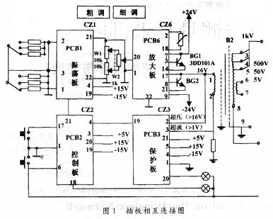
Analysis and Maintenance: Open the cover, first use the intuitive method to determine the point of failure, in the case of power and power off by looking, hearing, hearing, touch four intuitive sense. If no obvious fault is found, continue the search using the test method. Referring to the connection diagram of the chassis interposer board and the circuit diagram of the amplifier board shown in Fig. 1, first check the coarse and fine adjustment potentiometers W1 and W2 with the multimeter to see if the resistance value changes smoothly with the rotation of the knob. Then check the components of the amplifier board. In the inspection, it needs to be disconnected from the external circuit so as to avoid mutual influence and no actual parameters can be detected. The amplifier board is pulled out of the complete machine, and the seven transistors that make up the power amplifier, BG1, BG2, BG6-6, BG6-7, BG6-5, BG6-1, BG6-2, and potentiometers W6-1, W6, are sequentially inspected. 2 other components. After the amplifier board is inserted into the machine after inspection and repair, turn on the power and slowly adjust the output to the maximum. Use the multimeter's AC voltage profile to measure the output voltage of the primary terminal of transformer B2 to be 16V. If the voltage is normal, the output transformer's failure is ruled out. Continue to use the multimeter's DC voltage range to measure the voltage on terminal 21 of the on-off control board PCB2 to the ground voltage, which should be +2V for switch-on and -5V for switch-off. The terminal 18 voltage to ground should be +0.2-0.7V (indicator light on) or +12V (indicator off). If not normal, it can be judged that the fault source is in the continuity control board; if the voltage is normal, the fault may be in the oscillation board PCB1. The voltage between the terminals 21 and 22 of the PCB 1 should be 1.6V. If there is no voltage, it is estimated that the reason for the failure is that the oscillating plate stops and therefore does not have normal operating conditions. Continue to look for the components on the oscillating board. The focus of the inspection is on the oscillating board's op amp BG1-3, which is extremely bad. If the oscillating plate starts to oscillate normally, then the voltage between the terminals 20 and 22 of the magnified board PCB6 should be 1.6V. If it is much smaller than this reference value or there is no voltage, the connection between the oscillating plate PCB1 and the amplifying plate PCB6 can be judged openly. Or short circuit. Check the fault point and then perform line processing or replace components. 

Three-table calibrator faults can be divided into three types: performance fault, precision fault and stability fault. If it is a performance failure, it is necessary to pass the test of various parameters of the circuit board to troubleshoot the output transformer, amplifying board, oscillating board, and switching control board in the AC-DC signal path. If it is an accuracy fault, check the header digital panel and the oscillation board. If it is a failure of stability, it is necessary to judge whether the actual output fault or display fault, such as the actual output instability, should check the amplifier board, AC-DC conversion board and rectifier circuit; if the display instability, should check the display circuit and header; such as In both cases, all the above circuits should be checked.
Symptoms: Press the "ON", "OFF" button after power on, the output indicator does not change
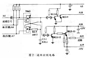
Analysis and Maintenance: This fault phenomenon belongs to the performance fault in the instrument fault. The DO30-B type digital meter calibrator mainly consists of 50/60/400Hz oscillator, power amplifier, protection circuit, AC/DC conversion and detection circuit. , standard resistors and power supply components. Obviously, the source of the fault should be locked in the protection circuit. The protection circuit is composed of two parts, the on-off control circuit PCB2 and the overload protection circuit PCB3. The on-off control circuit consists of an integrated circuit T063 and four transistors that control the output of the oscillator. The overload protection circuit consists of two op amps and five transistors that act as overload protection. Based on this circuit structure principle, combined with the fault phenomenon (no change in the indicator lamp after power on), the problem is not in the overload protection circuit, so the fault scope is further narrowed down and only the on-off control circuit part is searched. The circuit diagram of the on-off control circuit is shown in Figure 2. The working principle is as follows: T063 constitutes a bistable circuit, 6 pins are connected to R2-5, C2-1, when the instrument power is turned on or the “OFF†button is pressed, T063 Pin 8 outputs a high level, while BG2-8 is on, BG2-9 is off, and the output indicator is off. At the same time, BG2-12 turns on, BG2-13 turns off, and a break signal is output, turning off the oscillator output switch. No actual power output. When the “ON†key is pressed, T063 is toggled and pin 8 outputs a low level. The above four transistors are now turned to the opposite state, the corresponding output indicator is on, the oscillator output switch is on, and the output has a power output. According to the working principle, first check the solder joints of R2-5 and C2-1, check whether the parameters are abnormal, if the open circuit is re-welded, replace the new components if the components are damaged. Then turn on the power and check the output of the 8-pin T063 to see if there is any flip when pressing the “ON†and “OFF†keys. If not, T063 is damaged and replace the T063 component.
.