Measurement of boiler steam flow and its solution
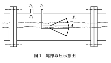
In the use of boiler steam flow meter, it really overcomes and solves many shortcomings and deficiencies of traditional differential pressure meters, and has been well received by users. However, some problems have also arisen. The most common problem is the measurement of steam flow. In Figure 1, PH and PL are the pressure signals for the positive and negative pressure taps; P1 and P2 are the pressures in the V cone segment. ‎Multi Process Welder
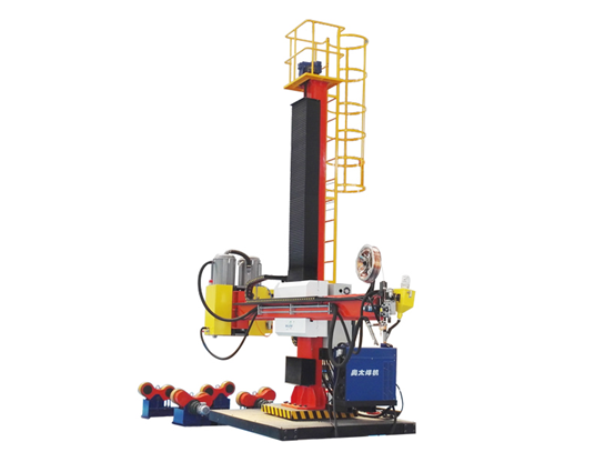
1. The guide rail is rectangular;
Multi Process Welder,Miller Multi Process Welder,Multi Process Welding Machine,Multi Welding Machine Shandong Buluoer Intelligent Technology Co., Ltd. , https://www.buluoermachine.com
In the case of steam shutoff during intermittent steam operation, sometimes the instrument always has unequal spurious flow indications, and checking the boiler steam flowmeter does have a differential pressure. Even if the installation specification is reasonable and the zero adjustment is normal, this problem still exists.
Especially when measuring wet saturated steam, this problem is even more pronounced. It can only be solved by increasing the small signal cutoff, but it often results in the normal flow being cut off.
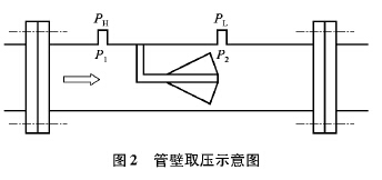
In the boiler steam flowmeter to measure the false flow at the end of the V cone resulting in the measurement of false flow of steam, its structure has been improved, and the negative pressure measurement port has been changed to the wall of the pipe. This method is called “take wall "Pressure", as shown in Figure 1 for the tail pressure structure, Figure 2 for the wall pressure structure.
The boiler steam flow meter solves the above problem by using the wall pressure. 
The boiler steam flowmeter with pressure from the wall changes the position of the negative pressure detection port. The original pressure measurement structure has a negative pressure measurement port at the end of the cone.
The negative pressure is transmitted to the transmitter through the measuring tube. During the transmission process, when the saturated steam or wet gas is measured, the condensed water accumulates in the negative pressure measuring tube, which affects the negative pressure transmission and causes distortion, resulting in the process valve. After shutting down, the flowmeter has a false flow display.
The wall pressure structure has changed the position of the tail pressure take-off port. It takes the pressure on the pipe wall like the positive pressure, eliminating the transmission error of the negative pressure measuring tube and ensuring the measuring accuracy of the instrument. 
2. It has the characteristics of large bearing capacity, good stability and low deflection.
3. Use the fork to lock the column device to prevent the skateboard and the beam from falling, to prevent the accident from causing the beam to fall.
4. It is widely used in the automatic welding processing of large-scale cylinder workpieces and structures. It is an automatic and efficient auxiliary machine that guarantees welding quality, improves production efficiency and improves working environment.
