Application of PLC Control in Electrostatic Precipitator System
Buy Leaf Springs,Leaf Spring Bolts,Helper Leaf Springs ,Car Leaf Springs Airui Brake Systems Co., Ltd. , http://www.wfbrakeplate.com
2. Electrostatic precipitator system process and basic principle 
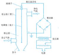
Electrostatic precipitators pass high-voltage direct current on two metal dust collectors (anodes) and corona electrodes (cathodes) with large differences in radius of curvature, and maintain a sufficient amount of dust-containing gas (referring to the general dust-laden flue gas, not Corrosive and highly toxic ionized electrostatic fields (see Figure 1). Electrons, anions, and cations generated when the dust-laden gas is ionized in an electrostatic field are adsorbed on the dust passing through the electric field, and the dust is charged by the charge itself. The charged dust moves to electrodes with opposite polarity (collecting dust and corona) under the action of the electric field force and deposits on the electrode, thereby achieving the purpose of separation of dust and gas. When the dust deposited on the electrode reaches a certain thickness, the dust is dropped into the lower ash hopper by means of dust collection pole and corona polar rapping mechanism, and the dust is discharged through the ash discharge system, and the purified gas is discharged. From the outlet of the electrostatic precipitator into the atmosphere [1].
3, system composition 
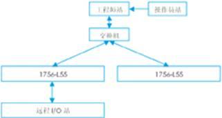
Taking the electrostatic precipitator of the 400m2 sintering machine head of Jinan Iron and Steel Works as an example, the electrostatic precipitator automatic control system for the head of the 400m2 sintering machine consists of 2 ablogix50001756-l55plc and 2 PCs, of which one ablogix5000plc sets up a remote For i/o stations, two upper computers are used for the operator station and the engineer station (see Figure 2).
4, control function 
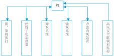
The main function of plc in the electrostatic precipitator system is to control all low voltage equipments to automatically run and remotely monitor the high voltage rectifier power supply equipment. The control of low voltage equipments generally has two manual and remote automatic control methods. The controlled equipment includes cathode rapping, Anode rapping, ash hopper discharge valve motor, wall vibrator, insulator heat preservation beam electric heater, hopper heat preservation electric heater, ash bucket level gauge, flue gas inlet and outlet temperature display, insulator heat preservation beam temperature display, sound wave Ash removal device, ash conveying system, safety interlock of high-voltage power supply equipment and remote monitoring [2] (see Figure 3). The following is a brief introduction to the automatic control method.
4.1 Control of cathode and anode vibration The cathode and anode vibration of the electrostatic precipitator is transmitted from the motor to the cathode and anode rapping mechanism through the transmission shaft, so that the accumulated dust on the cathode and anode plates is shaken down to the ash bucket. in. The plc system uses the time relays in the controller to control the yin and anode vibrating motors to operate in accordance with a certain time rule. The state of the motor is monitored and protected according to the contactor and the return signal of the thermal relay corresponding to the rapping motor. The general control law of cathode and anode vibration is as follows: the yin and anode vibration cycle of an electric field is the shortest, and the subsequent radian period of each electric field is gradually lengthened. The specific time needs to be determined according to the test conditions and process parameters when the electrostatic precipitator is just put into production. With 24 hours for the total rapping cycle, the nighttime operation cycle is shorter than the daytime operation cycle [3]; the yin and anode rapping operations are coordinated with each other, but the rapping cycle is calculated independently and the anode rapping is longer than the cathode operation time. High intensity; rapping feedback signal only plays a role of status monitoring and protection, and does not participate in the cycle operation control; to save energy, the rapping operation feedback signal is interlocked with the high-voltage rectifier power supply equipment, when a large number of rapping operations, high-voltage rectifier power supply The device operates at a low voltage or stops to achieve a jerk, which saves a lot of energy.
4.2 Insulator heat preservation beam electric heater control The plc system controls the electric heater through the temperature return signal detected by the temperature detection device in the insulator heat insulation beam to prevent the temperature in the heat insulation beam from falling below the dew point temperature, and the surface of the cathode insulator is dew condensation. Creepage or creeping discharge occurs on the surface of the insulator. The working voltage of the dust collector cannot be raised and the dust remover cannot work normally. The electric heater of this system has two power sources, which can realize high and low power heating. When the temperature in the heat-preservation beam is close to the dew point temperature, plc controls the electric heaters to heat all the two ways to increase the temperature of the heat-insulating beam as soon as possible; when the temperature is at the dew point When the temperature does not reach the set temperature, the single-way heater heats up slowly to maintain the temperature; when the temperature is higher than the set temperature, the heating is stopped. The plc system also monitors and protects the status of the electric heater based on the contactor and thermal relay return signals.
4.3 Control of ash hopper discharge valve motor and wall shaker The ash hopper discharge valve motor is used to switch the electric control valve when the ash bucket discharges ash. Plc automatic control of the ash hopper discharge valve motor and the hopper wall vibrator is realized according to the ash bucket level meter return signal. When the material level meter high material level signal returns to plc, plc controls the ash hopper discharge. The valve motor is turned on and the wall vibrator is interlocked to vibrate; when the level indicator low level signal returns to plc, plc controls the ash hopper discharge valve motor to close and the wall vibrator interlock stops. When the level switch control is not used or there is a fault in the level switch, the ash hopper discharge valve motor and the hopper wall vibrator can also be periodically controlled according to the empirical operating time. The specific time can be set according to the site conditions, but the ash hopper The unloading ash valve motor must have a certain cooperation relationship with the wall vibrator or be interlocked and operated together, otherwise it will cause the unloading of ash to be unsmooth and even cause ash clogging.
4.4 Control of Ash Conveying System The ash conveying system uses the mechanical dry ash conveying method. The ash conveying system is composed of a scraper, a scraper, a bucket lifter, an unloading valve motor and a humidifier. The control of the ash conveying system is similar to the belt flow control. When the ash hopper discharges the ash motor, the ash hopper ash discharge valve is opened, and the scraper corresponding to this row of ash hopper is interlocked, and the other ash hoppers are controlled by the unloading ash. Reasonably, each scraper can operate independently or simultaneously. When any ash bucket corresponding to the operation of the scraper, the assembly scraper interlocking operation, bucket elevator interlock operation, the dust ash scraped into the unloading ash warehouse, when the controller received a high level of material unloading hopper In the signal, the dust discharging valve motor, the unloading ash box vibration, and the humidifier interlocking operation will discharge dust.
4.5 Safety Interlocking and Remote Monitoring of High-voltage Power Supply Equipment All high-voltage rectifier power supply equipments of electrostatic precipitators have their own controllers. The network interfaces of these controllers are different. Take the serial communication as an example, the plc system can be collected through the serial port. The controller and the dedicated module matched with the logix5000 communicate with the controller, which can realize the remote control of the high-voltage rectifier equipment by the plc system, and can also monitor the operating status and parameters of the high-voltage rectifier equipment. The safety interlock is a program specially designed for the high voltage power supply equipment. When the remote control high voltage power supply equipment is started, the safety interlock signal of the rectifier transformer and the three-point isolation switch returning to the plc must meet the conditions, otherwise the high voltage power supply equipment is not allowed to start. The lock plays a significant role in personal safety and equipment operation when servicing the equipment.
4.6 Control of Acoustic Wave Cleaning Device Acoustic wave cleaning device is a system independent of electrostatic precipitator. The function is to completely clean the dust inside the precipitator when the electrostatic precipitator is stopped. Discharged. Therefore, the control of the acoustic wave cleaning device by plc is often performed by a centralized manual operation mode. When the operation is clicked, the acoustic wave cleaning device is cleaned once according to a fixed sequence, and the operation time can be controlled by the time relay, and the cycle is performed within the specified time. Ash removal.
5. Conclusion plc control In the application of 400m2 sintering machine head dust removal system in Jinan Iron and Steel Works, it can be seen that the plc system can significantly improve the level of automation, control performance, and intelligence of the electrostatic precipitator system. And the maintenance workload is greatly reduced, and the equipment failure rate is also greatly reduced. The plc control has direct influence and practical significance on realizing the intelligence and automation of the operation of the electrostatic precipitator, improving the operation of the electrostatic precipitator, increasing the dust collection efficiency of the electrostatic precipitator, prolonging the service life of various components and saving energy. .