Through the introduction of a simple CNC milling part and its CNC milling program, we can further understand the structure, characteristics and common code meanings of CNC milling program. The following figure shows a part drawing of a contour profile. The contour depth is 5mm. CNC programming adopts knife center programming. The coordinate point shown in the figure is the tool position coordinate value of the tool center.

Figure CNC milling programming example
(1) CNC milling program (see the following table)
Table CNC milling processing program
Program content
Program description
The beginning of the program
O6666;
The program number is O6666
N1;
Program N1
G54G90G17G21G94G49G40;
Create workpiece coordinate system, absolute programming, XY plane, metric programming, feed mode defined as mm/m, cancel tool length compensation
G0X300.0Y300.0 Z300.0;
The spindle moves to the safe position of X300.0Y300.0 Z300.0
M06 T09;
No. 9 end mill
M03S3600F680;
The spindle rotates forward, the speed is 3600RPM, the feed speed is 680mm/m
Program content
G0 X260.0Y180.0Z30.0;
The tool moves quickly to the starting point (X260.0, Y180.0, Z30.0)
X20.0;
The tool moves rapidly in the X direction (X20.0, Y180.0, Z30.0)
Y40.0;
The tool moves rapidly in the Y direction (X20.0, Y40.0, Z30.0)
G1Z-5.0;
Lower knife to (X20.0, Y40.0, Z-5.0) position
X40.0;
The tool is linearly interpolated in the X direction to the tool location (X40.0, Y40.0, Z-5.0)
Y100.0;
The tool is linearly milled in the Y direction to the tool location (X40.0, Y100.0, Z-5.0)
Continued
Program content
Program description
Program content
G03 X60.0Y120.0R20.0;
Tool counterclockwise circular interpolation milling to tool location (X60.0, Y120.0, Z-5.0), radius 20.0
G02 X100.0R20.0;
Tool clockwise circular interpolation milling to tool location (X100.0, Y120.0, Z-5.0) with radius 20.0
G03X110.0Y110.0R10.0;
Tool counterclockwise circular interpolation milling to tool location (X110.0, Y110.0, Z-5.0), radius 10.0
G01X210.0;
The tool is linearly milled in the X direction to the tool location (X210.0, Y110.0, Z-5.0)
G03X220.0Y100.0R10.0;
Tool counterclockwise circular interpolation milling to tool location (X220.0, Y100.0, Z-5.0), radius 10.0
G01Y60.0;
The tool is linearly milled in the Y direction to the tool location (X220.0, Y60.0, Z-5.0)
G02X200.0Y40.0R20.00;
Tool clockwise circular interpolation milling to tool location (X200.0, Y40.0, Z-5.0) with radius 20.0
G01X20.0
The tool is linearly milled in the Y direction to the tool location (X20.0, Y40.0, Z-5.0)
End of program
G0Z30.0;
Retract quickly away from the upper surface of the part
Y180.0
The tool is linearly milled in the Y direction to the tool location (X20.0, Y180.0, Z30.0)
X260.0
The tool is linearly milled in the Y direction to the tool location (X260.0, Y180.0, Z30.0)
G0X300.0Y300.0 Z300.0;
The spindle moves to the safe position of X300.0Y300.0 Z300.0
M5 M09;
Spindle stop, coolant stop
M30;
The program stops and returns to the main program
(2) NC program introduction
Most of the code looks very familiar, CNC milling program is divided into three parts of the beginning of the program, the program content and the end of the program.
Part 1 The beginning of the program
At the beginning of the program, the program number is mainly defined, and the parts machining coordinate system, machining tool, spindle start, coolant opening, etc. are called out.
O6666
To define the program number, the program number is O6666.
N1
The NC milling program consists of multiple programs. Each program can be a single column or linked together. To make it easy to distinguish, the program is defined as an N1 program.
G54G90G17G21G94G49G40
G54: To create a workpiece coordinate system instruction and select G54 as the current machining coordinate system. If no special indication is given, the CNC system defaults to the G54 coordinate system.
G90: Absolute programming.
G17: Machining plane Select XY plane.
G21: Select metric programming.
G94: Feed mode definition, select millimeters per minute in mm/m.
G49: Cancel tool length compensation.
G40: Tool radius compensation canceled.
G0X300.0Y300.0 Z300.0
The machine spindle moves to the safe position of X300.0Y300.0 Z300.0. In order to avoid the occurrence of collision or interference between the tool and the workpiece or the fixture during tool change, an effective method is to make the machine tool spindle and the machined part have a certain safety distance.
M06 T09
Select the tool command and adjust No. 9 end mill; at the same time, determine the offset value of No. 9 tool relative to zero point in the current machining coordinate system.
M03S3600F680
Define the rotation speed of the spindle, including the spindle positive rotation (M03), the rotation speed is 3600rpm (S3600), and the feedrate is defined as 680mm/m (F680).
The second part of the program content part
Program content is the main part of the entire program and consists of several program sections. Each program segment consists of several words, each of which consists of an address code and several numbers. Commonly used are the G and M instructions and the program segments of the axes.
G0 X260.0Y180.0Z30.0
The starting point is defined and the tool moves quickly to the starting point (X260.0, Y180.0, Z30.0).
G1Z-5.0
Place the tool vertically (X20.0, Y40.0, Z-5.0).
G03 X60.0Y120.0R20.0
The tool counter-clockwise circular interpolation milling contour, contour radius 20.0, G03 counter-clockwise circular repair instructions, milling from the tool location (X20.0, Y40.0, Z-5.0) to the tool location (X60. 0, Y120.0, Z-5.0).
G02 X100.0R20.0
The tool cuts the milling contour clockwise circularly, with a profile radius of 20.0, milling from the tool location (X60.0, Y120.0, Z-5.0) to the tool location (X100.0, Z-5.0), G02 is smooth Hourly arc check instruction.
Other program segments are similar in content.
Part 3 The end of the program
At the end of the program, the spindle of the machine tool is required to return to the starting point, ie, the starting point. At the same time, the spindle stops, the coolant is turned off, and the program selects to stop or end the program.
G0Z30.0
Quickly retract the knife away from the top surface of the part.
Y180.0 X260.0
The tool first returns quickly in the Y direction and then in the X direction.
X300.0Y300.0 Z300.0
The spindle of the machine tool quickly moves to the safe position of X300.0Y300.0 Z300.0.
M30
M30 stops the program and returns to the main program. During execution, the coolant, feed, and spindle are all stopped, and the NC program and the numerical control device are reset and returned to the original state before machining to prepare for the next program run and CNC machining restart.
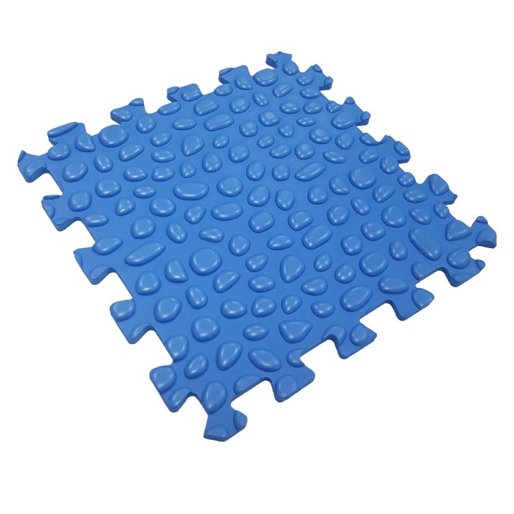
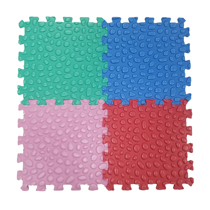
Bubbles Puzzle Mat
Bubbles Puzzle Mat is a new type foam puzzle mat with bubbles like or cobblestones like texture on the surface. Made from EVA foam material, it is not hard like a real cobblestone, but soft and flexible. The foam puzzle mat can be applied in the room, and use a tool of feet massage.


Just join the pieces together and place it on floor. It's easily disassembled as well for quick storage. Easy to clean with a wet cloth and neutral detergent.
Bubbles Puzzle Mat,Foam Puzzle Mat,Children Bubble Puzzle Mat,Bubble Jigsaw Puzzle Mat,Bubble Puzzle Foam Floor Mat,Foam Colorful Puzzle Mats
Huizhou City Melors Plastic Products Co., Limited , https://www.melorsmarine.com


